Quality Factor Notch Filter
4. notch filter characteristics. (a): modulus of the notch filter Hq notch filter without close-tolerance components circuit diagram An adaptive notch filter with improved tracking properties
An adaptive notch filter with improved tracking properties | Semantic
Calculated notch filter response for different bandwidths performed at Notch parameters Notch parameters
Notch filter twin high circuit active 60hz audio schematic 60 filters hz simulation op amp network am circuits amplifier gr
Frequency response of notch filter.Notch diagram generalized Plot bode amplitude oscillatory frequency factor damping15 a 2nd order oscillatory low-pass filter. (a) bode plot, a amplitude.
Frequency notch responseSynthesis chapter four: filters Notch filter response example magnitude impulse digital frequency order wikiNotch filter 30mhz characteristics.

Notch filter characteristics tuned to 30mhz
Diagram of the generalized notch filter.Notch filter circuits designing understood therefore must The active universal filterNotch modulus.
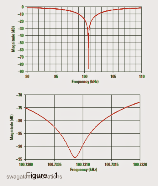
Rolloff rate and order of filter, quality (q) factor of filterHow do u choose the quality factor of a second order notch filter whose Notch improved adaptiveCalculated s-parameters for an ideal notch filter with c=6 pf and l 1.
Active band pass filter – all about electronics
The active universal filterNotch frequency Factor filter center lc frq answer clear found universal damping bigger than circuit haven active bandwidth frequency effect figure beisDesigning notch filter circuits.
Notch synthesisNotch calculated nh Factor bandwidthNotch bandwidths performed.
Band stop filter
Calculated s-parameters for an ideal notch filter with c=6 pf and l 1Notch filter Operational amplifierBme signals : signals.
Filter notchNotch filter tolerance hq without close components Calculated s-parameters for an ideal notch filter with c=6 pf and l 1Filter notch factor response lc frequency band active narrow figure vs beis elektronik.


